Swanneck conveyor
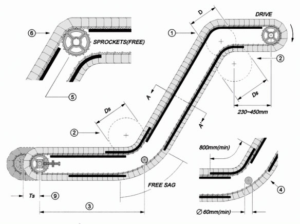
The supporting method for curved position of the incline conveyor is able to use plastic strips with lower friction, such as UHMW, HDPE, and Acetal, to be the bottom support. For the minimum curved diameter, please refer to the specification of Value D&Ds.
Backbend radius is a tight tension; please adopt the plastic strips with lower friction, such as UHMW, HDPE, and Acetal to manufacture it. For the minimum curved diameter, please refer to the specification of Value D&Ds.
The drive position in return way of swanneck inclined conveyor is also a kind of backbend radius; it is a loose tension. It may be designed with rollers or plastic strips with lower friction for supporting.
If the horizontal length between the idle sprocket and the curved position is more than 900mm, please install the wearstrips in the bottom of returnway.
When there is catenary sag appearing in the returnway of the swanneck inclined conveyor and the operating speed does not exceed 20M/min, it can be ignored and let it sag freely. However, if the speed exceed 20M/min, it is necessary to set up a roller with the diameter above 60mm to alleviate the jumping phenomenon that was resulted from the catenary sag of conveyor belt.
When adopting Hongsbelt drive sprocket to be the supporting method of curved angle and the operating speed is exceed 15m/min, it should be used the sprocket with more than 12 teeth, but please fix all the sprockets with retain rings and remove the guiding plate from the sprocket.
It is necessary to design with repressed rollers or strips on the swanneck inclined conveyor. The parallel pitch of strips can’t be lower than 100mm and it must set up the tension adjuster in the idle position to acquire proper tension.
Section A-A’ Design Specification
Inclined Conveyor
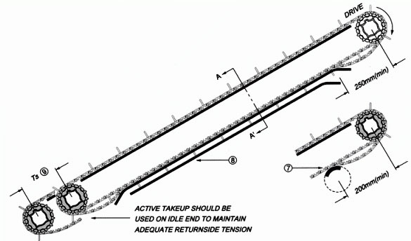
If the drive method of inclined conveyor is upper drive, the contact point between the drive sprocket center and the first roller or wearstrip in return way must maintain the interval over 200mm to let belt has enough space move and avoid it having an unusual engagement with sprockets and result in jammed situation. Please see the position 7 of the illustrate above.
If the belt width is more than 600mm, it should be installed center auxiliary wearstrips on the top of the flight in return way. Please refer to Section A - A’ and see the position 8 of the illustrate above.
TS is the tension adjustment; for the regulation of adjusting spacing, please refer to the chapter of Belt Length & Tension. Please see the position 9 of the illustrate above.
Section A-A’ Design Specification
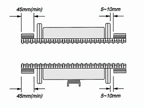
Type EL
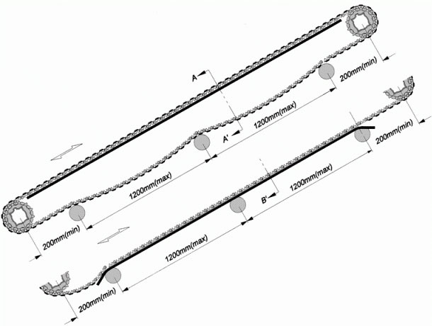
The spacing between the drive/idler sprocket and the first contact point in return way, no matter what the roller or wearstrip is, must be keep more than 200mm.
The maximum distance between all supporting rollers in return way does not more than 1.2M.
For other design points, please refer to Swanneck Conveyor and the illustration below.
For Series 200 EL and Series 300HDEL, they were processed and pasted TPE pieces on PP material belt. TPE is a high level skidproof material; the most common application is the skidproof handle of toothbrushes. It can be recycled without any misgiving about environmental protection, and blend with PP material to be an additive that can strengthen the tenacity. Regardless of inclining or declining, the angle of inclination can not exceed 40°.
Section Design Specification
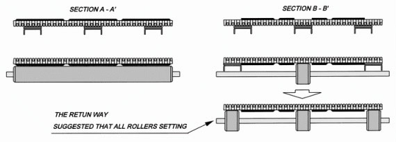
The minimum diameter of the return way roller is not able to less than 600mm. It can use rollers in return way in whole journey; however, the speed should be within 30M/min and the catenary sag should be controlled within 35mm to avoid the TPE flange striking rollers with big angle and result in bad operation.
It can also adopt the design method as the illustration, section B-B', shows above. For the illustration above, the wearstrips supported on both sides and the roller supported in the center. For the illustration below, it adopted rollers to support in the three parts. Both of them are the best method for design.
Backbend Radius DS
All HONGSBELT conveyor belts serial products were assembled into a interlocked unit, it has the minimum reversing radius limitations; therefore, to make belt pass through the backbend area smoothly , please pay attention to the limitation of minimum diameter when designing the conveyor and refer to the table below for correcting radius of each series ).
HONGSBELT conveyor belt is capable to operate in inclined conveying design; basically it is available to reach any inclining angle with correct calculation of backbend radius diameter.
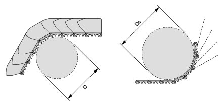
unit : mm
| Series | 100 A | 100 B | 200 A | 200 B | 300 | 400 | 500 | 501B | 502A/B | |
| D | Without Side Guard | 250 | 250 | 135 | 120 | 200 | 45 | 150 | 150 | 180 |
| With Side Guard | 250 | 250 | 135 | 120 | 200 | - - | - - | 180 | 200 | |
| DS | Without Side Guard | 250 | 200 | 150 | 120 | 220 | 45 | 150 | 180 | 200 |
| With Side Guard | 280 | 230 | 300 | 290 | - - | - - | - - | 200 | 230 | |
Backend Radius Hold Down Explanation
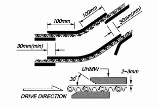
Backend radius of the inclined conveyor system is a very common design for achieve the inclined conveying purpose. Therefore, it is necessary to take the smooth motion of belt surface or bottom into account when designing the hold down area. Please refer to the illustration above. As to the proper material for contacting and wearing with the belt, we recommend to adopt HDPE or UHNW material when the speed is less than 20 M/min; if the speed is more than 20 M/min, please adopt UHMW or TEFLON material.
Please process or grind the hold down position to 30 degree chamfer in the entrance to assure the conveyor with the smooth movement.
Angle & Capacity
If the capacity of transporting goods is too big, in order to avoid articles falling from the transporting procedure, it is not suitable to adopt lower side guards or design with a steep gradient in the inclined conveyor. Please pay special attention to the relative relation between the capacity of goods and the inclining angle, and refer to the illustration below.
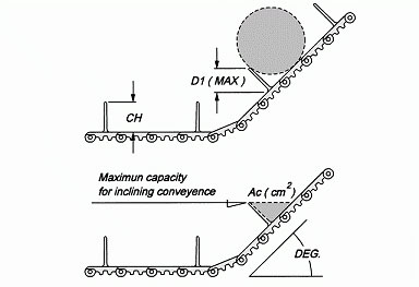
Unit : CH=mm, D1= mm, Ac=cm2
|
DEG. |
15° | 20° | 25° | 30° | 35° | 40° | 45° | 50° | ||
| CH | 25 | D1 | 23 | 22 | 21 | 20 | 19 | 17 | 16 | 15 |
| Ac | 11 | 8 | 6 | 5 | 4 | 3 | 3 | 2 | ||
| 50 | D1 | 46 | 45 | 46 | 40 | 38 | 35 | 32 | 29 | |
| Ac | 46 | 34 | 26 | 21 | 17 | 14 | 12 | 10 | ||
| 75 | D1 | 70 | 67 | 64 | 61 | 57 | 53 | 48 | 42 | |
| Ac | 104 | 77 | 60 | 48 | 40 | 33 | 27 | 23 | ||
| 100 | D1 | 9. | 90 | 86 | 81 | 76 | 70 | 64 | 57 | |
| Ac | 186 | 137 | 107 | 86 | 71 | 60 | 50 | 41 | ||
| 125 | D1 | 117 | 113 | 108 | 102 | 95 | 88 | 80 | 71 | |
| Ac | 291 | 214 | 167 | 136 | 111 | 92 | 77 | 65 | ||
| 150 | D1 | 140 | 136 | 129 | 122 | 114 | 106 | 96 | 86 | |
| Ac | 490 | 360 | 281 | 227 | 186 | 156 | 130 | 109 | ||
For the result of loading capacity, please multiply value Ac with the effective width (cm) of flight .
Decline Conveyor
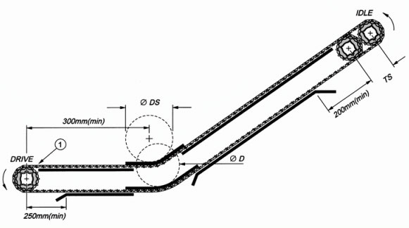
Generally, for the design of decline conveyor system, we recommended to use type A or type B as the conveyor example. the transporting system is designed to drive at the bottom of conveyor as the position 1 of the illustrate below shows. For the value D & DS, please refer to Backend Radius Ds in left menu.
Type B
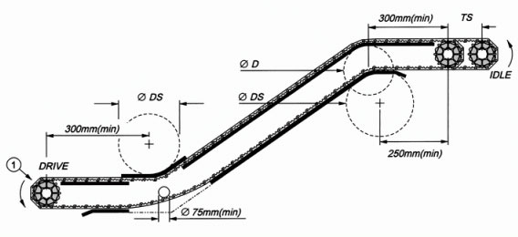
If it is necessary to adopt type C as the conveyor design example, the adjusting spacing Ts should be kept at least 75mm. For the value D & DS, please refer to Backend Radius Ds in left menu.
Type C
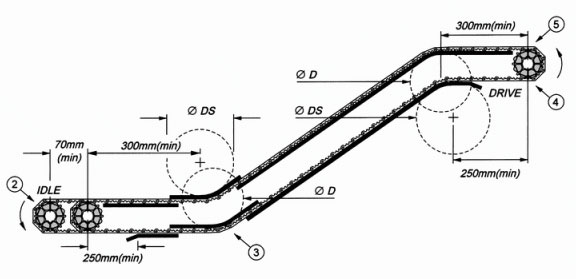
The proper tension of position 3 should receive from the tension adjustment of position 2.
In order to make the backend radius at position 4 and the bottom of drive sprocket to receive the best corresponding angle and proper tension, and benefit the operation of the belt, it is necessary to adjust tension at position 2 and hold down at position 3.
If it is unable to receive the proper tension through position 2, it will result in the hold down effect could not receive from position 3 and 4. That may cause the jostling phenomenon of belt spacing that would result in the folding angle at position 5. The sprocket will have a wrong engagement and result in pausing and failing.
Type D

Multi Backend Radius
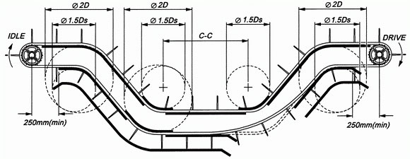
For multiple backend radius design, the wearstrips should be placed at the return way to support the top of flight, in order to avoid belt deforming or collapsing form the conveyor frame. Please see the illustration below.
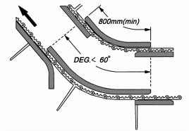
If the incline bending angle is less than 60 degree, it can use hold down rail made of UHMW engineering plastic to hold down both side of belt lateral end. For the reference of D & DS value please see the following table at the end of this page below.)
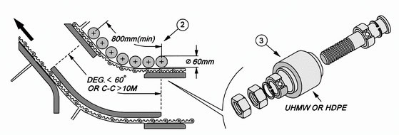
If inclining angle is greater than 60 degree, we recommend to using driven roller to positioning under the belt, as to decrease the abrasion area and reduce the return way tension.
Bearing style hold down roller should construct through a precision processing, it must tighten fixed on the angle steel of conveyor frame by screw supporting as illustrate shows above. (For the reference of D & DS value please see the following table at the end of this page below.)
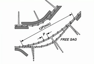
The distance of return way catenary sag recommended to save at least 12 pieced module width, in order to make return way having enough space to release tension.
Notes
HONGSBELT modular belt is very suitable to apply in all kinds of high temperature environment, such as steam and hot water submerged etc. When adopting HONGSBELT belt in high temperature environment , please use stainless steel rods and steel links to overcome the deflection phenomenon that caused from the backend radius. We have lots of experience in high temperature application, and we are willing to serve you. For the related points of designing the conveyor system, you can negotiate with us all the time.
Hold Down Modules
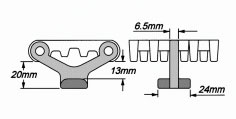
Incline conveyor can suspend hold down modules (HDM), it is a guiding device particularly designed for the backend radius on the return way of conveyor. Hold down modules are in T shaped design, and they are installed in the underside of the belt, to hold down the belt. It can reach the result of incline without holding down the position of backend radius, and do not adopt rollers to support belt on return way.
Description of HDM Installation
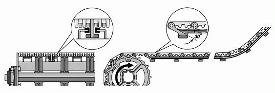
When installing HDM, please adopt low friction coefficient materials as UHMW or HDPE at the contact area. Do not let HDM contact with metal material directly. It may damage the conveyor belt because of the friction. In order , Processing the wearstrip at the entrance into 30 degree chamfer to get the better operation of HDM. Please refer to the illustrate above.
Side Prevention
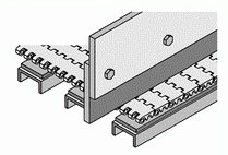
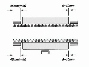
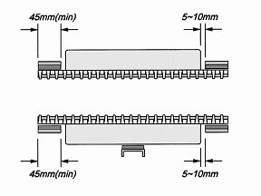
HONGSBELT modular conveyor belt can also attach with fixed type side guards to prevent the products fall from belt edge. High density engineering plastic material should be used for the construction of side guards attachment, and must reserve safety spacing between belt and fixed type side guard. Moreover, it is necessary to avoid using soft material such as PVC, PU or fiber weaving material to rub against belt surface directly, it might possibly cause damage to the belt surface. Please refer to the illustrate below.

Large And Non Contamination Product
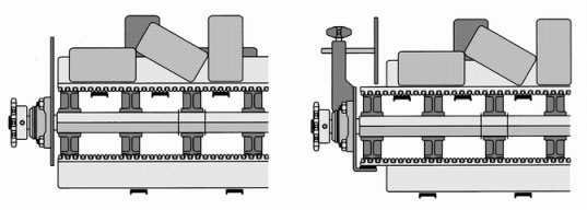
The application above is generally for no contamination or large size products conveyance. This design example is extended the main structure of the conveyor directly, to form the function as side guards.
Notes for Belt Bending Gap

The structure of HONGSBELT products is the modular interlocked unit. Therefore, no matter how tight the side preventions are, the triangular gap will still appear on the bending area of belt. Please refer to the illustrate above. It has to be taken notice during designing or considerated to adopt HONGSBELT accessories, side guards. In addition, the object such as HDPE or UHMW warp, plastic bag fringe, residue burr of plastic goods or other flat and tiny object may possibly permeate into belt gap or slot.
These foreign objects may cause the conveyor to jamming situations or interference the belt rotation, if not considerate to attach with HONGSBELT side guard for side fall prevention, we suggest the minimum thickness of the conveying goods must at least double size larger than belt triangular gap.
Small Particles
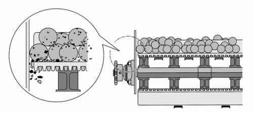
Small objects and easily contamination materials such as biscuits, dry fruit, and fodder are quite easy to fall from the belt surface. The small particles of these materials will pile up on the conveyor structure, and drop into the chink of the conveyor belt. For preventing the small object permeate into the belt and conveyor structure, we recommend you to design your conveyor as illustrate below; it will get better protection to the equipment.
