Support Method
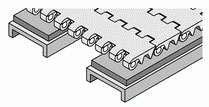
The best supporting method of HONGSBELT modular conveyor belt is adopting wearstrips as the support under the belt. To avoid adopting rollers to support the belt , because the spacing between rollers will cause the unusual vibration at modules linking position, and sprockets will make a wrong engagement with the conveyor belt. There are two normal ways of wearstrips supporting; one is parallel arrangement and another is chevron arrangement. HONGSBELT conveyor belts are able to be supported in both two supporting ways.HONGSBELT serial products are suitable for various kinds of wearstrips’ design.
Parallel Arrangement
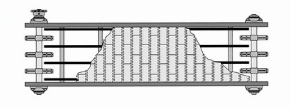
The straight wearstrips are placed on the frame and paralleled with the transporting direction of the belt . It’s the most popular design for HONGSBELT products adopting.
Installation Explanation for Parallel Wearstrip
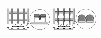
The best arrangement for wearstrips is interlacing the wearstrips with lateral cross method, to avoid the spacing becoming big because of the thermal expansion and contraction caused by temperature change. It would cause the spacing in groove shape and result in noise and unusual pause because of the conveyor belt sinking during operation.
Regarding to the arrangement for the pitch, please refer to Pitch Diagram in left menu.
Pitch Diagram - P of Series 100

Notes
The graph above is the spacing data of supporting wearstrip center; these data are approximations and for reference only. Please allot it averagely and smaller than the curve data while installing.
Pitch Diagram - P of Series 200 Type A

Notes
The graph above is the spacing data of supporting wearstrip center; these data are approximations and for reference only. Please allot it averagely and smaller than the curve data while installing.
Pitch Diagram Table - P of Series 200 Type B

Notes
The graph above is the spacing data of supporting wearstrip center; these data are approximations and for reference only. Please allot it averagely and smaller than the curve data while installing.
Pitch Diagram Table - P of Series 300

Notes
The graph above is the spacing data of supporting wearstrip center; these data are approximations and for reference only. Please allot it averagely and smaller than the curve data while installing.
Pitch Diagram - P of Series 400

Notes
The graph above is the spacing data of supporting wearstrip center; these data are approximations and for reference only. Please allot it averagely and smaller than the curve data while installing.
Pitch Diagram - P of Series 500

Notes
The graph above is the spacing data of supporting wearstrip center; these data are approximations and for reference only. Please allot it averagely and smaller than the curve data while installing.
Chevron Wearstrips Arrangement
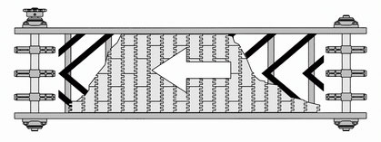
To place the wearstrips in the chevron arrangement; it can support the whole width of the belt and the wear condition of the belt will be distributed averagely.This arrangement is also good for heavy loading applications. It can distribute the loading averagely and reduce the supporting breadth of the belt; its guiding effect in the rectilinear motion is also better than straight wearstrips. It is the best supporting method we recommend.
Installation of Chevron Wearstrips Arrangement

While installing chevron arrangement wearstrips , please pay special attention to the opposite relation between the horizontal tangent angle θ of wearstrips and pitch arrangement, P1. Please process the wearstrips into an inverted triangle at the contacting point of belt and wearstrips; it will make the belt operate more smooth.
Chevron Wearstrip Arrangement Pitch Table - P1
unit : mm
| Loading | ≤ 30kg / M2 | 30~60kg / M2 | ≥ 60kg / M2 | ||||||||||
| DEG. | 30° | 35° | 40° | 45° | 30° | 35° | 40° | 45° | 30° | 35° | 40° | 45° | |
| Series | 100 | 140 | 130 | 125 | 115 | 125 | 120 | 115 | 105 | 105 | 100 | 95 | 85 |
| 200A | 100 | 90 | 85 | 80 | 80 | 75 | 70 | 65 | 65 | 60 | 55 | 50 | |
| 200B | 90 | 80 | 75 | 70 | 70 | 65 | 60 | 55 | 55 | 50 | 45 | 40 | |
| 300 | 150 | 145 | 135 | 135 | 135 | 130 | 120 | 110 | 130 | 125 | 115 | 110 | |
| 400 | 90 | 80 | 75 | 70 | 70 | 65 | 60 | 55 | 55 | 50 | 45 | 40 | |
| 500 | 140 | 130 | 125 | 115 | 125 | 120 | 115 | 105 | 105 | 100 | 95 | 85 | |
Please refer to the table above for the pitch range to match up the average width of conveyor and adjust the pitch yourself.
Sag Area Solution
While transporting the heavy loading or operating in unstable situations, such as rolling and sliding; the structural sag will appear at the connecting position because of the gravity oppression. It will result in the belt surface forms a sag between the wearstrips and drive/Idler sprocket. It will make a wrong engagement of belt and influence the transporting procedure.
To avoid the situation mentioned above, we recommend to adopt the strengthen wearstrip for reinforcing the belt support.The key point of design is making the wearstrips approach to the center position of the sprocket.
The Closest Distance from Wearstrip to Sprockets Center
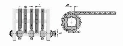
The corresponding dimension of B1, please refer to the table below. The wearstrips are installed at location 1 and B1 was installed at location 2. For pitch between lateral cross arrangement, please refer to Pitch
Diagram in left menu.
| Series | B1 |
| 100 | 26mm |
| 200 | 13mm |
| 300 | 23mm |
| 400 | 5mm |
Wearstrips Processing
Wearstrips are usually made of TEFLON, or UHMW, HDPE compound plastic material. There are various standard sizes can be purchased in the market. These wearstrips can be attached to C shape angle steel of conveyor frame by welding, or fastened with screws directly. While installation, please make sure to reserve enough spacing for thermal expansion and contraction of plastic material that caused by temperature change. We recommend the length of plastic material that was covered on wearstrips is not able to over 1500mm.
When the temperature of operating environment is less than 37°C, please adopt method A. When the temperature is higher than 37°C, please adopt method B. For better and smooth operation, please process the spacers on both ends of the wearstrip into an invert triangle before installation.
Wearstrips Material
Materials for spacers of wearstrips are TEFLON, UHMW, and HDPE in general. They are processed to suit for all kinds of working environments. Please refer to the table below.
| Material | UHMW / HDPE | Actel | |||
| Dry | Wet | Dry | Wet | ||
| Rotating Speed | < 40M / min | O | O | O | O |
| > 40M / min | △ | O | O | O | |
| Ambient Temperature | < 70 °C | O | O | O | O |
| > 70 °C | X | X | △ | O | |
Low Temperature
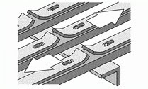
In the low temperature environment, the wearstrips were made of plastic material, UHMW or HDPE, would be deformed because of the physical change, the thermal expansion and contraction. It will affect the working efficiency of the conveyor.
Therefore, if the range of temperature different between high temperature and low temperature is more than 25°C, it is necessary to adopt wearstrips with metal chute to prevent the spacer split off .
High Temperature
HONGSEBLT modular conveyor belt is suitable to apply in all high temperature environments, such as 95°C steam and 100°C hot water submerged etc. But we do not recommend to adopt spacers which made of HDPE, UHMW and other engineering plastic material as the support in the environment with high temperature we mentioned above. It is because they would expand and deform seriously in high temperature environment; it would damage the conveyor.
Only if the structure with special design, and the wearstrip is limited in the regular track after calculating and deduct the expansion size can overcome the persecution that caused from the high temperature environment. We have abundant experience to provide you technique description for reference. Please contact with HONGSEBLT technical department and the local agencies for further information.
Plastic material will become soft in the environment with high temperature; overweight loading would increase the friction and result in the excessive burden that could damage belt and motor. Therefore, you have to reduce the belt strength to 40% with stainless steel links in the working environment which temperature is higher than 85°C.
According to our experience for a long time, the transporting speed will be slow in high temperature environment. We recommend you to adopt the stainless steel products with the smooth surface in wet or submerged environment, and it contact area is not able to over 20mm. You can also adopt the stainless steel with TEFLON surface process, it is good at reducing the friction factor.
